General topics
Centrifugal fans: selecting flow rate, pressure and impeller
A centrifugal fan transfers energy to air or gas through an impeller. Its performance in the system depends on the relationship between the equipment curve and the resistance of ducts, filters, hoods and accessories.
The process and emission sources
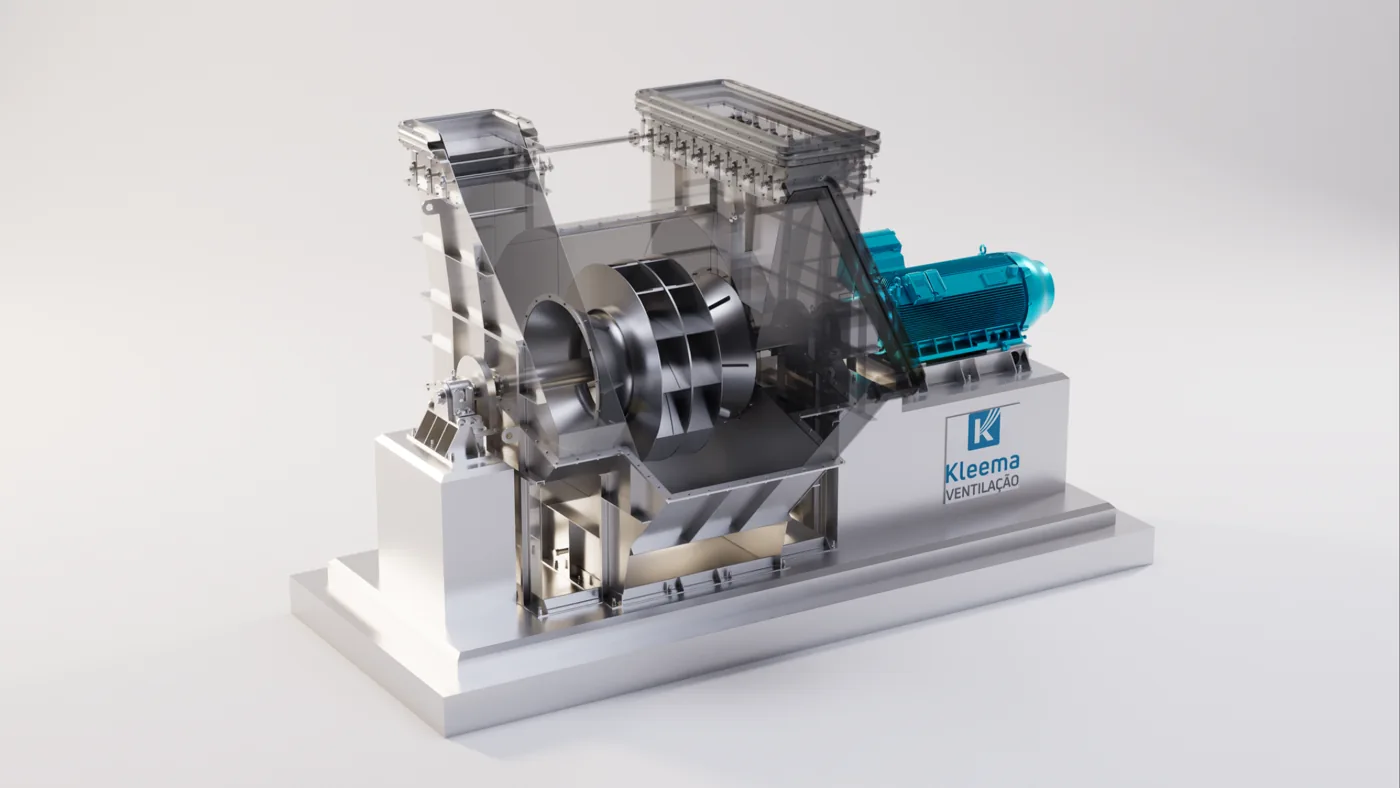
The impeller accelerates the gas and the casing directs its passage, converting some of the flow energy into pressure. In the installed circuit, flow rate results from the interaction between the fan characteristic and the resistance of hoods, ducts, filter and discharge. Therefore, a stated flow rate without reference pressure and density is insufficient for equipment selection.
Temperature, altitude and composition influence density. The curve may need correction to represent the process gas, while mechanical and thermal limits must be checked separately. The fan must meet normal conditions and relevant varying conditions.
Characteristics that guide engineering
Flow rate, pressure, density and temperature must be specified at the same reference conditions. Impeller geometry must be compatible with solids presence, wear and operating range, as well as the intended efficiency.
Solution configuration and sizing
Impeller selection considers efficiency, solids presence, adhesion and wear. Radial geometries may be considered for certain particle-laden streams; backward-curved blades and airfoil profiles can improve efficiency under compatible conditions. No geometry is superior in every application, and the impeller name does not replace the performance curve.
Power across the operating range, speed, transmission, base, seals and ease of inspection must also be checked. Bends, dampers and transitions close to the inlet or outlet can produce non-uniform flow and reduce performance relative to the reference test. This effect must be addressed in the installation rather than merely compensated for with a larger motor.
Design parameters
| Parameter | How to assess it | Engineering decision |
|---|---|---|
| Flow rate and pressure | Specify at operating conditions | Define the required operating point |
| Density and temperature | Match to the curve | Correct performance and power |
| Range and installation | Assess curves and connections | Avoid selection based on a single value |
- Assess the system curve.
- Check losses and installation effects.
- Select a motor for the expected range.
- Check speed and mechanical limits. Balancing and alignment complement aerodynamic selection.
Performance, diagnostics and maintenance
An efficient operating point must reconcile required flow rate, pressure and efficiency. Excessive throttling of an oversized system dissipates energy; reducing speed may be an alternative where compatible with the process and assembly. The approximate relationships between speed, flow rate, pressure and power rely on assumptions and do not eliminate the need to check the installed curve.
During commissioning, recording speed, electrical power, pressures, flow rate and damper positions establishes a useful baseline. If measured flow is below the expected value, direction of rotation, actual resistances, air ingress and installation effects must be investigated before concluding that power is insufficient.
Illustrative example: flow rate alone does not determine power
Consider a hypothetical demand of 100,000 m³/h and 3,000 Pa total pressure, under the conditions for which the fan was selected. The flow rate is approximately 27.78 m³/s, and the power transferred to the gas is Q × Δp ≈ 83.3 kW.
With a hypothetical fan efficiency of 75%, shaft power would be approximately 111.1 kW. Assuming direct drive and a motor efficiency of 95%, with no other drive losses in this example, estimated electrical power would be 117.0 kW. The motor's rated power still requires analysis of the operating range and design criteria.
Two fans advertised for 100,000 m³/h may have very different pressures and efficiencies. Comparison must use the same operating point and density reference. The example does not select a model or recommend the efficiencies used; it demonstrates why pressure, efficiency and gas conditions must accompany any stated flow rate.
Fan commissioning
Field verification must relate speed, flow rate, pressure and power to the expected conditions. Ducts close to the inlet or outlet can alter performance; catalog selection must therefore be confirmed in the installed arrangement.
Further technical reading
Does your process need an assessment?
Talk to Kleema engineering about sizing, modernization and operating conditions.
Talk to engineering ↗