General topics
Bag filter sizing: flow rate, area and pressure drop
Sizing a bag filter means matching process flow rate to dust characteristics, filter medium and operating conditions. Installed area alone does not define design quality.
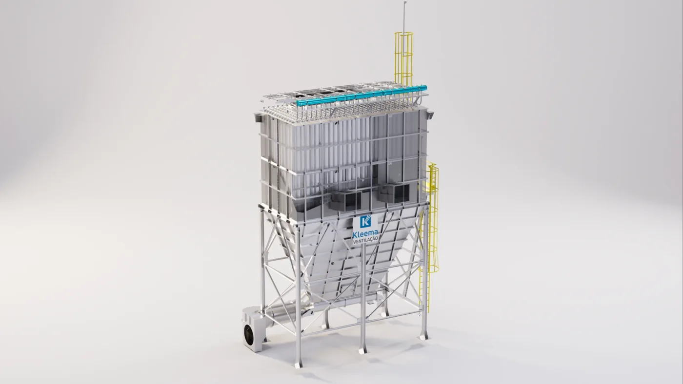
The process and emission sources
Specification starts with the stream reaching the filter: actual flow rate, temperature, pressure, moisture, gas composition and dust properties. Particle size distribution, concentration, bulk density, adhesion and abrasiveness influence layer behavior and cleaning. Stating only factory production or a desired filtration area leaves fundamental decisions unresolved.
Continuous operation, peaks and startup and shutdown conditions must also be distinguished. If flow rate is specified at normalized conditions, it must be matched to conditions as it passes through the filter. Directly comparing actual m³/h and Nm³/h can cause sizing errors.
Characteristics that guide engineering
Filtration velocity is flow rate divided by filtration area, using consistent units. It must not be confused with upward velocity between bags, which is determined by the free-flow cross-section and relates to dust transport and re-entrainment.
Solution configuration and sizing
Filtration velocity, or air-to-cloth ratio, is calculated as Q/A. Flow rate must use a time unit consistent with the selected velocity. This relationship guides area selection, but its choice depends on dust, filter medium, cleaning and applicable experience. A larger area does not automatically correct poor distribution or insufficient discharge.
Upward velocity is a different quantity: it represents flow through internal free cross-sections, especially between bags. Values incompatible with material behavior can impede the fall of dust released during cleaning and encourage re-entrainment. Gas inlet, spacing, diffusers and bag arrangement must be assessed together, taking care not to create impact zones or deposits.
Design parameters
| Parameter | How to assess it | Engineering decision |
|---|---|---|
| Flow rate at filter conditions | Match reference conditions and units | Calculate area and velocities |
| Dust properties | Characterize adhesion and particle size distribution | Select medium and cleaning |
| Free cross-sections and distribution | Assess internal geometry | Reduce impact and re-entrainment |
- Assess gas distribution and internal velocities.
- Select the air-to-cloth ratio for the application.
- Size cleaning and discharge.
- Monitor differential pressure. Low pressure drop can have different causes and must be interpreted alongside flow rate and element integrity.
Performance, diagnostics and maintenance
Pressure drop includes the resistance of the element and dust layer. Its behavior depends on flow rate, cleaning and material characteristics and should not be reduced to a single ideal value. An increase may indicate greater loading, deficient cleaning or adhesion; a decrease may reflect reduced flow, a loading change or retention failure.
The design must integrate area, distribution, cleaning, discharge and fan selection. During commissioning, the performance reference must include flow rate, differential pressure, emissions and process conditions. This approach allows assessment of whether the system meets its objective without confusing a well-selected component with guaranteed performance of the entire installation.
Illustrative example: filtration area and units
Consider, solely to demonstrate the calculation, a flow rate of 60,000 m³/h at actual filter inlet conditions and a hypothetical filtration velocity of 1.0 m/min. First, flow rate must be converted: 60,000 ÷ 60 = 1,000 m³/min. The calculated area would be A = Q/v = 1,000 ÷ 1.0 = 1,000 m².
If an area of 1,200 m² were used for the same flow rate, average velocity would be approximately 0.83 m/min. This does not demonstrate that the second configuration will be better in every process: cost, cleaning, internal distribution and dust behavior remain relevant. The value of 1.0 m/min is an assumption in the example, not a design recommendation.
Two casings with 1,000 m² of fabric may have different internal free cross-sections. Therefore, the same air-to-cloth ratio does not imply the same upward velocity. The area available during any compartment unavailability and the flow rate that will continue to be treated under that condition must also be defined.
Interpreting differential pressure
The value must be read alongside flow rate, cleaning condition and filter history. A change may indicate an alteration in dust loading or flow and should not automatically be attributed to saturation or failure of a bag.
Further technical reading
Does your process need an assessment?
Talk to Kleema engineering about sizing, modernization and operating conditions.
Talk to engineering ↗